PART IV: Developing Expert Applications
Chapter index
PART IV:
Developing Expert Applications
Customizing and Programming
AutoCAD
Analyzing usage habits and patterns
Current work habits -- when to program
To restore your original Existing profile:
Setting up a working directory and profile for this
chapter
Switching between profiles while working in AutoCAD
Launching AutoCAD from icons on the desktop -- Command
line switches
Creating a custom UNLEASHED
AutoCAD icon on the Windows Desktop
Customizing the user interface
Drag and drop the easiest way to create custom
toolbars
Launching Windows calculator from a toolbar icon
Running a VBA macro from a toolbar icon
Creating an icon on the toolbar to switch/flip
profiles.
Deleting an Icon from a toolbar
Using the Diesel Macro Language
Comparison of Diesel and LISP time functions.
Using Diesel expressions in the pull down menu
Creating a script file to setup five layers
Setting up two text styles from a script file
Creating a script file “snippet”
ScriptPro program from Autodesk
Launching the Autodesk Express tool's ScriptPro
program from a toolbar icon.
Why would one use VBA in AutoCAD 2000 when LISP is so
well supported in AutoCAD?
In the VBA editor create a new module
Using LISP functions from a toolbar icon.
Running Diesel expressions from the command prompt via
AutoLISP.
Managing project search directories with PROJECTNAME
Helpful tips on customizing AutoCAD
Opening the Visual Basic Editor
Running the SwitchProfile macro
Distributing your VBA programs within a drawing.
Distributing your VBA programs as a project file.
How to get to AutoCAD 2000’s VBA Help reference.
AutoCAD VBA sources on the Internet
Visual Basic (VB) sources on the Internet
MNL file – an automatically loading lisp file associated with a menu.
Creating a Hyperlink to a product specification
documents.
Creating a Hyperlink to a Microsoft word document:
Creating a Hyperlink to an Adobe acrobat PDF document
Creating a Hyperlink to an AutoCAD drawing detail.
Open, Copy, or Edit a Hyper link in a drawing
Creating Hyperlinks to Internet documents.
Creating a Hyperlink to a website.
Creating a Hyperlink to a document on the Internet
Creating a Hyperlink to a DWF on the Internet
Visual Basic Customization Issues with AutoCAD
Visual LISP™, AutoLISP® and General Customization
Issues
Plotstamp program from Autodesk
Customizing and Programming AutoCAD
This chapter focuses on how to customize AutoCAD using profiles, menus
and programming to suit user requirements
Analyzing usage habits and patterns
Current work habits -- when to program
In order to create effective AutoCAD customizations, you as the customize/programmer/user must understand how you (or others) use AutoCAD. Typically, I start customizing AutoCAD (for own use) when I find that I am doing a repetitive task. Rather than be bored with the chore of doing the same thing repeatedly in AutoCAD, I will look at how I am currently doing the task and think about what tools I will use to customize AutoCAD. I also have found it beneficial, when programming/customizing AutoCAD, to look over the shoulders of AutoCAD users and see how they use AutoCAD. Your analysis of how/what to program should include the following checklist. What are the important functions that need to be automated what would save time and make the day go faster for the user? How can AutoCAD be customized to address repetitive issues or complex calculations? There are a huge arsenal of tools available to the programmer to customize AutoCAD, LISP, VBA, Menu tools bars, to name a few. What programming tool fits the problem? What type of user interface is required to make the program easy for others or myself to use? Is the project worth doing? Will the customization be used? Does a non-programming solution exist within AutoCAD? Has someone else solved this problem and is it available free on the Internet? Is a professinal 3rd party applicaion available (at a reasonable price) that could be used?
Usability
All customizing of AutoCAD for other users can fall by the wayside if the end user (possibly yourself) does not use them. My favorite AutoCAD user quote on upgrading from r12 to r14 is “I don’t have the time to learn this new stuff and become more productive”. Obviously, ease of use of any customization (for yourself or others) is key to any AutoCAD customization. I have two favorite programming quotes from instructors. The first quote is from my LISP instructor Gunnar Capan “50% of all programming efforts should be creating an interface that the user can understand to use your program”. The second quote is from my Visual Basic instructor Pat Vacca “Users would rather be doing anything else except using your program”. Ideally, all customization of AutoCAD incorporates ease of use and increases the productivity of the user. Keep in mind that AutoCAD users just want to get their work done -- not learn how to use your fancy new program!
Creating user profiles
Warning!Before you begin customizing the User interface and working through the programming examples in this chapter, you will need to save and export the current AutoCAD profile. If you do not save and export the current AutoCAD profile settings, you may experience several nasty results during the hands on customization portion of this chapter! |
To save and export the current AutoCAD profile:
- From the AutoCAD command prompt type: OPTIONS
- From the Options form, select the Profiles tab
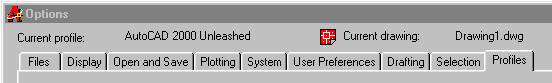
Figure 1 Profiles tab
- Press the button Add to List…
 in the Profiles section
 - In the profile name type: Existing
- In the profile description type: Existing profile before starting the AutoCAD 2000 unleashed customization exercise
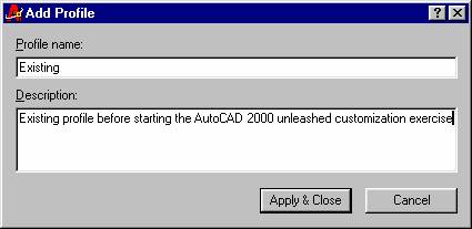
Figure 2 Add Existing Profile
- Press the Apply & close button on the Add Profile dialogue box.
- Select the Existing profile in the Available Profiles window
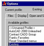
- Press the Set Current button.
Export the Existing profile:
- Press the Export… button
- Export the profile as Existing.arg
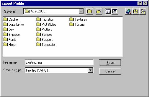
Figure 3 Export Existing Profile
What have we just accomplished? You now have a working profile stored on your hard drive. The Existing profile gives you a “snap shot” profile of a working AutoCAD configuration. You can now fall back to this profile if anything goes wrong or if you need to set your AutoCAD back to the way, it was running before doing the exercises in this chapter.
To restore your original Existing profile:
- From the AutoCAD command prompt type: OPTIONS
- From the Options form select the Profiles tab
- Press the Import button
- Select the Existing.arg file from the Import Profile dialogue box.
- Press the Open button on the Import Profile dialogue box
- Press the Apply & Close button on the Import Profile dialogue box
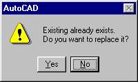
- When prompted for if you want to replace the Existing profile press the Yes button
Setting up a working directory and profile for this chapter
- From Windows Explorer, create the working directory for this chapter C:\MYACADAPP
- Using the Options form, create a new profile called AutoCAD 2000 Unleashed
- Set the AutoCAD 2000 Unleashed profile to the current profile
- Select the Files tab
- Select the Support File Search Path folder
- Press the Add… button
- Type in the path to the working directory for this chapter C:\MYACADAPP
|
Tip! Alternately use the browse button to search for an existing directory. This method ensures that you have no typos in the directory name. |
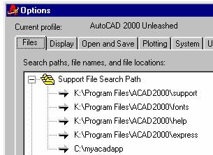
Figure 4 adding C:\myacadapp to the AutoCAD Search Path
- Press the Apply button at the bottom of the Options form.
- Select the Profiles tab.
- Export the AutoCAD 2000 Unleashed profile to C:\MYACADAPP\unleashed.arg
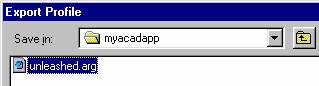
Figure 5 Export unleashed profile
Creating a Reset profile
You may want to create a Reset profile to take you back to a “vanilla” out of the box standard AutoCAD with no customizations. To create a reset profile:
- From the AutoCAD command prompt type: OPTIONS
- From the Options form, select the Profiles tab
- Press the button Add to List…
- In the profile name type: Reset
- In the profile description type: Plain Jane AutoCAD 2000 with no customizations.
- Press the Apply & close button on the Add Profile dialogue box.
- Select the Existing profile in the Available Profiles window
- Press the Set Current button
- Press the Reset button
- Press the Yes button
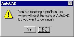
Figure 6 Reset warning dialogue box
Switching between profiles while working in AutoCAD
If you have been following along doing the exercises in this chapter, you should now have three profiles: Existing, AutoCAD 2000 Unleashed, and Reset. To switch between profiles during an AutoCAD session, open the Options form, select the Profiles tab and double click on the Profile you wish to use. We will be switching between profiles quite frequently for the rest of this chapter with menu customization and integration. You will quickly see how customized versions of AutoCAD are affected and managed in different profiles.
Launching AutoCAD from icons on the desktop -- Command line switches
At some point in time in your AutoCAD customization career, you will want to have AutoCAD load with your custom “flavor” of AutoCAD. Autodesk does this with its vertical market products like Architectural Desktop, Mechanical Desktop, and Land Development Desktop (or DirtTop as we affectingly call it). So, how do they do it? Autodesk uses custom icons on the Windows desktop (and Start button menus) to launch “flavors” of AutoCAD. For instance, by right clicking on the AutoCAD Mechanical Desktop icon on my Windows desktop and going to the properties option and looking at the Short cut tab, I can see that Autodesk is launching AutoCAD Mechanical Desktop using a command line switch that sets up AutoCAD to use the Mechanical Desktop profile. Voila! Autodesk uses profiles to control how its flavors of AutoCAD load. You can use this method for accessing your own UNLEASHED flavor of AutoCAD.
Creating a custom UNLEASHED
AutoCAD icon on the Windows Desktop
Next, you need to create a custom Unleashed icon on your desktop. This will allow you to start AutoCAD with the Unleashed profile.
- Right-click and drag your mouse over your AutoCAD 2000 desktop icon.
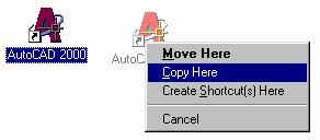
Figure 7 Copying the AutoCAD 2000 desktop icon
- Select the Copy Here option
- Right-click the new AutoCAD 2000 icon
- Select the Rename option and rename AutoCAD 2000 to Unleashed

Figure 8 AutoCAD Unleashed Icon
- Right-click the Unleashed Icon
- Select the Shortcut tab in Properties dialog box.
- Edit the parameters in the Target box to include: "C:\Program Files\ACAD2000\acad.exe" /p "c:\myacadapp\unleashed.arg"
- Edit the Start in box: c:\myacadapp
Figure 9 AutoCAD Unleashed Icon Properties
At this point, you should now have a custom AutoCAD Unleashed icon on your Windows desktop. Each time you load AutoCAD from this icon, you will load an AutoCAD session with the AutoCAD 2000 unleashed profile. We are now ready to get on with the business of customizing of AutoCAD!
Customizing the user interface
The customizations to the user interface for this chapter will be done using AutoCAD with the profile AutoCAD 2000 Unleashed. If you have not already created the AutoCAD 2000 Unleashed profile, please go back to the beginning of this chapter and do so now! If you already have AutoCAD running, switch profiles to AutoCAD 2000 Unleashed -- see the section Switching between profiles while working in AutoCAD. Alternately, launch AutoCAD with the Unleashed flavor from the Windows desktop -- see the section Launching AutoCAD from icons on the desktop -- Command line switches. Now that you are running AutoCAD 2000 with the Unleashed “flavor”, we can start customizing the look and feel of AutoCAD. The first customization is relatively minor. We will start by changing the background color of AutoCAD drawing space (Model tab background). To do this will work once again with the Options form.
- From the AutoCAD command prompt (or right click over the command line area with your mouse and select Options…)
- Select the Display tab
- Press the Colors… Button
- From the Color: list box select More…
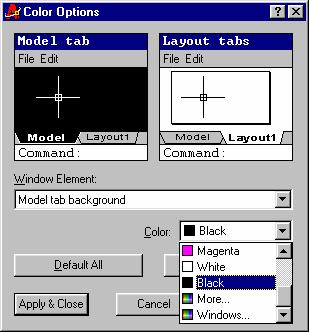
Figure 10 Color Options form
- In the Color: text box type: 8
- Press the OK button
- Press the Apply & Close button
- Press the OK button on the Options form
You have now changed the background color of the AutoCAD Model tab background to AutoCAD’s color 8 (a dark gray background). However, why do this? Aha, a history lesson is in order… Back in the good old days of DOS (dinosaur riding was also popular), and when video card refresh-rates were so slow, you could just about count them; the flickering affect of the monitors was pathetic. To compensate for the flickering affect of graphics in AutoCAD, the drawing area color was set to black. Setting the drawing screen to black has the same effect (persistence of vision) on the user as looking into the oncoming car’s bright headlights when driving at night. After the car has past, you are temporarily blinded. Therefore, by using a black background, the lines (or bright lights) persist between the flickering/flashing of the monitor. With the advent of the modern monitor and Video card, flickering is eliminated (when set at 70Hz or better) from user perception. I find that using a gray background in AutoCAD makes for less head aches and less eyestrain. Try using the gray background yourself for a day to “see” the results.
Customizing and adding menus
The customization and adding menus section for this chapter will be done using AutoCAD with the profile AutoCAD 2000 Unleashed. In the following exercise, you will create and load a new menu called unleashed.mnu in the directory C:\MYACADAPP
- Using Windows Explorer, open the folder C:\MYACADAPP
- Right-click inside of C:\MYACADAPP on the window pane to the left
- Select New | Text Document
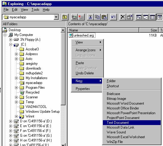
Figure 11 Creating a New | Text Document in C:\MYACADAPP
- Rename the “New Text Document.txt” to unleashed.mnu
- Press the yes button in the rename dialogue box
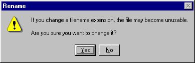
Figure 12 rename dialogue box
- Double click the unleashed.mnu to edit in notepad or write (depending on how you setup your AutoCAD editor)
Next, you will give the menu a name in the MENUGROUP section, setup a pull down menu in the POP1 section, and create an empty toolbar in the TOOLBARS section.
- Inside of the unleashed.mnu add:
***MENUGROUP=Unleashed
***POP1
[Unleashed]
[More custom menu stuff goes here]
***TOOLBARS
//This line is a comment
// Menu from AutoCAD 2000 Unleashed
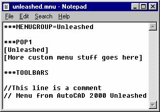
Figure 13 Editing the Unleashed.mnu in notepad
- Save unleashed.mnu
- Exit notepad
- From the AutoCAD command prompt type: MENU
Initially, the Select Menu file will open with the default Files type: as Menu Files (*.mnc, mns) since you have been working on the unleashed.mnu, it does not display in the Select Menu File dialogue box.
- Change the file type: to Menu Template (*.mnu)
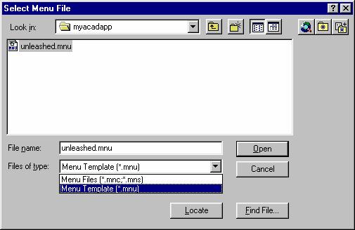
Figure 14 selecting the unleashed.mnu in the dialogue box.
- Select the unleashed.mnu
- Press the Open button
- Press the Yes button on the AutoCAD MNU file overwrite message box
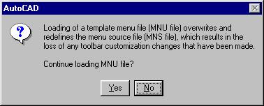
Figure 15 MNU overwrite message dialogue box
You should now have only one pull down in your unleashed flavor of AutoCAD.
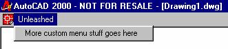
Figure 16 Unleashed menu loaded
Yikes! Where did the wrest of the menu pull downs go? Switch back to the Existing profile (of course you made the Existing profile earlier – if not Oh Oh!) to see that you have not fried your AutoCAD. You can now switch to the AutoCAD 2000 Unleashed profile with the sad and sorry looking single pull down.
Menu Extensions
Look in the folder C:\MYACADAPP. You should now have an unleashed.mnu, unleashed.mns, unleashed.mnc and an unleashed.mnr.
The term menu file actually refers to the group of files that work together to define and control the appearance and functionality of the menu areas. We will be concentrating on the MNU file and AutoCAD will be generating the other files for us in the background. The following table describes the AutoCAD menu file types.
|
File type |
Description |
|
MNU |
Template menu file. |
|
MNS |
Source menu file (generated by AutoCAD). |
|
MNC |
Compiled menu file. This binary file contains the command strings and menu syntax that defines the functionality and appearance of the menu. |
|
MNR |
Menu resource file. This binary file contains the bitmaps used by the menu. |
Base and Partial Menus
AutoCAD uses the concepts of base and partial menus. The base menu is the last menu loaded with the MENU command. In the Existing profile, acad.mnu is the base menu. In the AutoCAD 2000 unleashed profile, the unleashed.mnu is the base menu. So far, we have used the unleashed menu as the base menu and have only accessed this base menu from within the AutoCAD 2000 Unleashed profile. The next exercise focuses on how to integrate the unleashed menu as a partial menu to be loaded into an existing (full acad.mnu) menu structure. A partial menu is defined by Autodesk as “any menu that is loaded with the MENULOAD command”. Use the MENULOAD command to load in the unleashed menu into the Existing profile and arrange the menus on the menu bar.
- Right-click the AutoCAD command prompt area
- Select Options…
- Select the Profiles tab
- Double click the Existing profile in the Available profiles window
- Press the OK button on the Options form
You should now have AutoCAD looking the way everything was before you started this chapter.
- From the AutoCAD command prompt type: MENULOAD
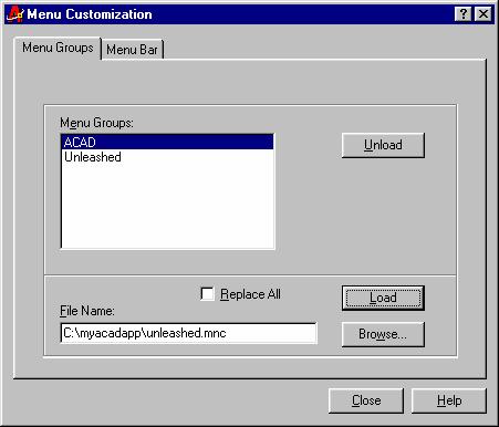
Figure 17 Menuload Menu Customization dialogue box
- Press the Browse… button
- Find the unleashed.mns in C:\myacadapp\unleashed.mnc and press Open
- Back in the Menu Customization dialogue box, press the Load button
- Select the Menu Bar tab
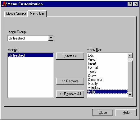
Figure 18 Menu Bar tab
- From the Menu Group: list box select Unleashed
- Highlight the Unleashed in the Menus: list box
- Highlight Help in the Menu Bar: list box
- Press the insert button
Look
at your AutoCAD screen; you have just inserted the Unleashed pull down between
the Window and Help pull downs.
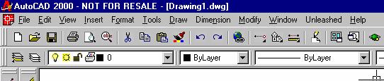
Figure 19 Unleashed pull down
inserted between Window and Help pull downs.
15. Press the Close button on the Menu
Customization dialogue box.
When you load a partial menu, AutoCAD uses the same procedure described previously to generate MNC, MNR, and MNS files. AutoCAD also loads the associated MNL file and DLL (resource file), if one exists.
Customizing the toolbars
Smiley faces be gone!
Using partial menus, users and developers can make effective use of multiple menus. Keeping your custom menu separate and doing all customizations to the custom menu when it is the base menu, will force AutoCAD to update the base menu resources. Picture the following scenario. When doing customizations to AutoCAD with a partial menu loaded and making changes on the fly to a toolbar within the partial menu, all changes and menu icon resources are saved back to the base menu (the resources for the custom partial menu are NOT updated). Therefore, if you are using a base acad menu and make changes to a partial menu (i.e. unleashed.mnu) the bitmap resources for the custom menu toolbars are then stored in the acad.mnr. Oh oh! When you go reload/recompile, the base acad.mnu by using the MENU command, all of the resource information for the icons in your custom toolbars now will have smiley faces! Obviously, this is not a good situation. Always do your customizations to your custom menu ONLY when the custom menu is the base menu.
Drag and drop the easiest way to create custom toolbars
 Sure and you thought I was going to show you
the hard way of had-blaming the unleashed.mnu!
Not!
Sure and you thought I was going to show you
the hard way of had-blaming the unleashed.mnu!
Not!
Switch to the AutoCAD 2000 Unleashed profile.
- Right-click the AutoCAD command prompt
- Select Options…
- Select the Profiles tab
- In the list box Available profiles: Double click AutoCAD 2000 Unleashed
- Press the OK button on the Options form.
You should now be back to that sad and sorry lonely single unleashed pull down.
- From the AutoCAD command line type: TOOLBAR
- From the Toolbars form press the New button
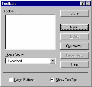
Figure 20 Toolbars form
- Fill in the New toolbar form:
Name: AutoCAD
2000 Unleashed
Menu
Group: Unleashed
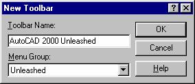
Figure 21 Creating the New AutoCAD 2000 Unleashed
Toolbar
You should now have an empty toolbar floating in the middle of your AutoCAD screen that looks like this:
![]()
Figure 22 Empty AutoCAD 2000 Unleashed Toolbar
- On the Toolbars form, press the Customize… button.
- Select Standard from the Categories list box
- Scroll downs in the icon display area until you find an Icon that looks like a calculator.
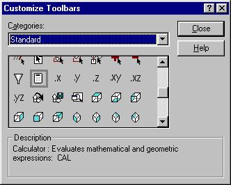
Figure 23 Find the Calculator Icon
- With the left mouse button, drag the calculator icon from the icon selection area to the AutoCAD 2000 Unleashed toolbar.
- Release the left mouse button.
Your AutoCAD 2000 Unleashed toolbar should look like this:
![]()
Launching Windows calculator from a toolbar icon
Next, modify the button properties to change the default settings of the calculator icon to start the windows calculator
- Right-click the calculator icon in the AutoCAD 2000 Unleashed toolbar.
- On the Button Properties form fill in the following:
Name: Windows Calculator
Help: Start
the Windows calculator
Macro: ^C^C^C(startapp “calc”)
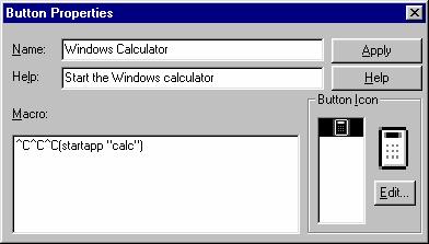
Figure 24 Calculator Icon Button Properties
- Press apply on the Button Properties form
- Press the X button in the top right hand corner of the Button Properties form
- Press the Close button on the Customize Toolbars form
- Press the Close button on the Toolbars form
- Place your mouse over the calculator icon in the AutoCAD 2000 Unleashed toolbar. Notice how the tool tip come up with “Windows Calculator” also notice that the status area below the command line now displays “Start the Windows calculator”
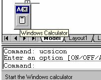
Figure 25 Mouse over the calculator icon
- Press the calculator icon
You should now see the Windows Calculator. We will go into more depth on how the (startapp “calc”) LISP function works later in this chapter. Open your unleashed.mns to view the additions of the toolbar information. After doing the above drag and drop toolbar customizations, my unleashed.mns now looks like this:
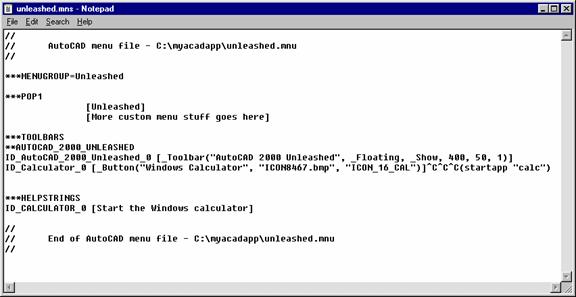
Figure 26 unleashed.mns in notepad after doing toolbar drag and drop
Take a close look at the format of the unleashed.mns; notice that the Windows Calculator calls an ICON.bmp for the picture file for the Calculator button. In the following exercise, you will give the calculator ICON.bmp a more meaningful name, make changes to the MNS file, save the MNS file as a MNU file and reload the unleashed. MNU
- From Windows Explorer find the unleased.MNS (c:\myacadapp\unleashed.mns)
- Double click the unleashed.MNS
- Go to the line in the file that reads “Windows Calculator”, “ICON.bmp”,
- Replace ICON.bmp with calc.bmp
- Also replace the second icon reference on this line to calc.bmp
- Save the unleased.MNS
- Save the unleased.MNS again using Save As
- Save As unleashed.MNU
- Exit the menu editor.
- From the Windows Explorer find the ICON.bmp
- Right-click the ICON.bmp file
- Use the Rename option and rename the ICON.bmp to calc.bmp
- Delete the following files in the c:\myacadapp directory: unleashed.mns, unleashed.mnc, unleashed.mnr
- From the AutoCAD command prompt type: menu
- Open the unleashed.mnu
You have now recompiled the unleashed.mnu with the calc.bmp. Using icon names that can you can understand makes finding and updating the toolbars much easier. Next, you will add another button to the AutoCAD 2000 Unleashed toolbar and draw your own icon.
- Right-click on the calculator icon in the AutoCAD 2000 Unleashed toolbar.
- Select the Customize… option
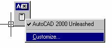
Figure 27 Right-click toolbar with Customize.... option
- Press the Customize… button on the Toolbars form
- From the Categories: list box (on the Customize Toolbars form) Select Custom categories
- Drag and drop the Blank Icon from the custom icon list.
- Right-click the new blank icon on the AutoCAD 2000 Unleashed toolbar
- On the Button Properties form fill in the following:
Name: Edit this MNS
Help: Launch Windows Notepad with this menu
Macro:^C^C^C(startapp
“notepad” “c:/myacadapp/unleashed.mns”)
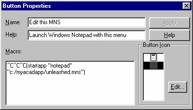
Figure 28 Button Properties for MNS editor
- From the Button Properties form select Edit
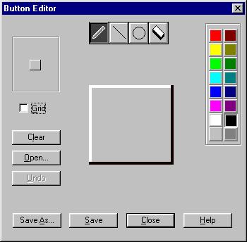
Figure 29 Button Icon Editor
Now you get to practice your artistic
skills and create a fancy notepad icon for your mns.
- From
the Button Editor form press Save As
- Save the icon as mnseditor.bmp
- Press the Close button on the Button Editor form
My AutoCAD 2000 Unleashed toolbar now looks like this: 
Switch to you Existing profile. Notice how the AutoCAD 2000 Unleashed toolbar contains your current unleashed customizations. Switch back to the AutoCAD 2000 Unleashed profile.
Running a VBA macro from a toolbar icon
With all this switching back and forth between profiles, now would be a good time to automate the process. The next exercise creates an icon that takes us from the AutoCAD 2000 Unleashed profile and the Existing profile or back. This icon will make use of a VBA macro that checks the current profile name and flips to the other profile.
Creating an icon on the toolbar to switch/flip profiles.
- Right-click the calculator icon
- Select the Customize… option
- From the Toolbars form press Customize…
- From the Customize Toolbars form drag and drop the Named View icon on to the AutoCAD 2000 Unleashed toolbar
- Right-click the Named View icon
- On the Button Properties form fill in the following:
Name: Switch Profiles
Help: Switch between Unleashed and Existing profiles
Macro: ^C^C^C-vbarun;c:/myacadapp/project.dvb!module1.SwitchProfile;
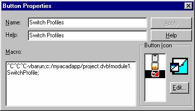
Figure 30 Switch Profiles Button Properties
Wait a minute! You have not written a VBA macro for this Icon! Skip ahead to the section called: Creating a VBA macro … Glad you are back!
- On the Button Properties form press the Apply button
- Close the Button Properties form
- Close the Toolbars form
- Try
out the new Switch Profiles icon!
Creating a toolbar flyout
To this point, you have been working with the AutoCAD 2000 Unleashed toolbar. In the next exercise, you will create another toolbar and access it from the AutoCAD 2000 Unleashed toolbar as a flyout toolbar.
- Right-click the calculator icon (or any icon on the AutoCAD 2000 Unleashed toolbar)
- Select the Customize… option
- From the Toolbars form, press the New button
- Fill out the New Toolbar form as follows:
Name: Unleashed Flyout
Menu Group: Unleashed
- On the Toolbars form, Press Customize…
- Drag and drop the following icons onto the Unleashed Flyout:
3D Pan, 3D Zoom, 3D Orbit, 3D Continuous Orbit, 3D Swivel, 3D Adjust Orbit, 3D Adjust Clip Planes, Front Clip On/Off, Back Clip On/OFF
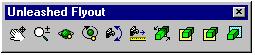
Figure 32 Unleashed Flyout Toolbar
- From the Custom Toolbars form, select the Categories: Custom.
- Drag and drop the blank Flyout icon from the Custom Toolbars form to the AutoCAD 2000 Unleashed toolbar.
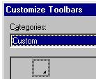
Figure 33 Custom Flyout Icon
- Right-click the custom flyout icon on the AutoCAD 2000 Unleashed toolbar
- Edit the Flyout Properties as follows:
Name: Unleashed Flyout
Help: Press Here for Unleashed Flyout
Associated Toolbar: Unleashed.Unleashed Flyout (highlight this option)
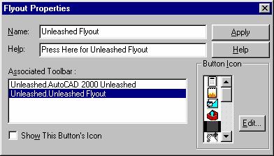
Figure 34 Flyout Properties form
- On the Flyout Properties form, press the Apply button
- Close the Flyout Properties form
- Close the Customize Toolbars form
- Close the Toolbars form
- Close the Unleashed Flyout toolbar (the one you just created)
- Press (and hold) the custom flyout icon on the AutoCAD 2000 Unleashed toolbar
- Select an icon on the flyout.
- Enjoy!
Displaying a missing toolbar
In the above exercise, you created flyout toolbar and then closed the toolbar. The Unleashed Flyout toolbar is on longer visible on the screen. To make this toolbar visible, do the following:
- Right-click the AutoCAD 2000 Unleashed toolbar
- Select Unleashed Flyout
- You can see the missing toolbar.
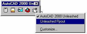
Figure 35 Displaying the Unleashed Flyout toolbar
Deleting an Icon from a toolbar
As you are busily dragging and dropping icons on to your custom toolbars, you will occasionally need to remove an icon from the toolbar. Possibly the icon has the wrong picture or the associated macro has been made obsolete by advances in the next release of AutoCAD. Whatever the reason, it is always good to know how to remove unwanted icons from a toolbar.
- Add an unwanted icon to the AutoCAD 2000 Unleashed toolbar (unless you already have an icon on the toolbar you want to remove)
- Right-click on the calculator icon (or any icon in the AutoCAD 2000 Unleashed toolbar)
- Select the Customize… option
- On the Toolbars form press the Customize… button
- Drag the unwanted icon from the AutoCAD 2000 Unleashed toolbar
- Drop the unwanted icon onto the AutoCAD drawing screen area
- Poof! The icon is now removed from the toolbar.
Using the Diesel Macro Language
Diesel is an acronym for Direct Interpretively Evaluated String Expression Language. Diesel is a macro language for altering the AutoCAD status line (with the MODEMACRO system variable), customizing menu items, and Rtext objects.

Figure 36 Filler up with Diesel
MODEMACRO
MODEMACRO is an AutoCAD system variable (and an AutoCAD command to access the MODEMACRO system variable). The MODEMACRO variable information is displayed in the Status area in AutoCAD (typically directly below the command prompt line).
When working with drawings that have long layer names, I sometimes find that not enough room is provided in the AutoCAD layer pull down list box.
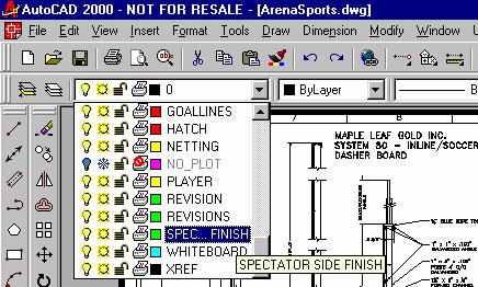
Figure 37 AutoCAD Layer Pull down list box
To display the current layer below the command prompt use the Diesel expression: $(getvar,clayer). This Diesel expression gets (using getvar) the current layer (clayer) variable in the current drawing. To display the current layer in the Status area do the following:
- From the AutoCAD command prompt type: MODEMACRO
- Type: Current Layer = $(getvar,clayer)
- Press Enter
- Change the current layer from the Layer list box
- Note status area now contains the current AutoCAD layer.
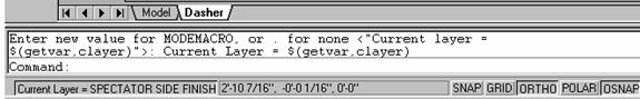
Figure 38 Modemacro with $(getvar,clayer)
 To return the status are off type MODEMACRO
(enter) . (enter)
To return the status are off type MODEMACRO
(enter) . (enter)
To have AutoCAD display the current command in the status area use MODEMACRO with $(getvar,cmdnames)
Comparison of Diesel and LISP time functions.
Although Diesel is less robust for programming than AutoLISP, Diesel does have an easier time evaluation function than AutoLISP. The following is a quick look at the amount of code that is required to return the Date and Time in Diesel as compared to AutoLISP.
|
In Diesel: $(EDTIME,$(GETVAR,DATE),H:MMam/pm DD/MO/YYYY,) |
In AutoLISP: (defun
c:date () (setq td (getvar "date")) (setq time (* 86400.0 (- td (setq j
(fix td))))) (setq j (- j 1721119.0)) (setq y (fix (/ (1- (* 4 j))
146097.0))) (setq j (- (* j 4.0) 1.0 (* 146097.0
y))) (setq d (fix (/ j 4.0))) (setq j (fix (/ (+ (* 4.0 d) 3.0)
1461.0))) (setq d (- (+ (* 4.0 d) 3.0) (* 1461.0
j))) (setq d (fix (/ (+ d 4.0) 4.0))) (setq m (fix (/ (- (* 5.0 d) 3)
153.0))) (setq d (- (* 5.0 d) 3.0 (* 153.0 m))) (setq d (fix (/ (+ d 5.0) 5.0))) (setq y (+ (* 100.0 y) j)) (if (< m 10.0) (setq m (+ m 3)) (progn (setq m (- m 9)) (setq y (1+ y)) ) ) ; Now print
the date. Year in Y, month in M, day in D (princ (fix y)) (princ "/") (princ (fix m)) (princ "/") (princ (fix d)) ; Determine
the clock time from the fraction of the day (setq hh (fix (/ time 3600.0))) (setq time (- time (* hh 3600.00))) (setq mm (fix (/ time 60.0))) (setq ss (- time (* mm 60.0))) ; Print the
time (princ " ") (princ hh) (princ ":") (princ mm) (princ ":") (princ ss) (terpri) ) |
 RTEXT/Diesel - Common
uses
RTEXT/Diesel - Common
uses
 The next two examples use the Rtext
object. Remote Text (Rtext) objects
display as normal text or Mtext objects do, but the source for the text is
either an external ASCII text file or the value of a DIESEL expression.
The next two examples use the Rtext
object. Remote Text (Rtext) objects
display as normal text or Mtext objects do, but the source for the text is
either an external ASCII text file or the value of a DIESEL expression.
Creating a Date Stamp
In the following exercise, you create a Date Stamp Rtext object with information about the drawing name, user, time and date.
1. From the AutoCAD command prompt type: RTEXT
2. Next type: Diesel
3. In the Edit Rtext text window type the following:
$(getvar,dwgprefix)$(getvar,dwgname) By: $(getvar,loginname)
Date:
$(edtime,$(getvar,date),MON"," DD YYYY)
Time:
$(edtime,$(getvar,date),HH:MM am/pm
Creating an Xref Stamp
Create an Xref Stamp to display all of the external reference drawings attached to the current drawing (XREFs).
1. From the AutoCAD command prompt type: RTEXT
2. Next type: Diesel
- In the Edit Rtext text window type:
$(xrefs)
Using Diesel expressions in the pull down menu
The original text for this section included example
exercises that incorporated Diesel functions to place text date and time stamps
in the drawing using standard AutoCAD text objects. However, my Diesel code that has worked from
AutoCAD r12 through r14, no longer works in AutoCAD 2000. I wasted several hours trying to make the
example code work, looking in the Autodesk newsgroups, and searching the
Autodesk website. Then, I recalled a
recent AutoCAD User Group meeting in
I was able to have AutoCAD correctly interpret the Diesel expressions for menu labels in a pull-down. The following works, but the original text for this section was much better! Oh well!
- From the AutoCAD 2000 unleashed toolbar, select the Edit the MNS icon
- In the unleashed.mns, under the ***POP1 section, find the line [More custom menu stuff goes here]
- Replace the line [More custom menu stuff goes here] with
[$(eval,"Current
Layer: "$(getvar,clayer))]
[$(eval,"Drawing
name: "$(getvar,dwgprefix)$(getvar,dwgname))]
[$(eval,"Time:
"$(edtime,$(getvar,date),H:MMam/pm))]
[$(eval,"Short
Date: "$(edtime,$(getvar,date),MO"/"DD"/"YY))]
[$(eval,"Long
Date: "$(edtime,$(getvar,date),Month"
"DD""","" "YYYY))]
4. Save the unleashed.mns
5. From the AutoCAD command prompt type: Menu
6. Select C:\myacadapp\unleashed.mns
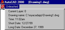
Figure 39 Diesel Expressions in a pull down menu
Creating macros
Creating a script file
Script files can also be used for automating repetative tasks. Due to the inherent simplicity of the script file, anyone that can type in commands at the AutoCAD command prompt can create a script file. The script file is a text file that can contain the same commands as the user would type in AutoCAD. Script files typically do not allow user interaction. Once a script file is loaded, it trundles on its marry way until it ether blows up (due to a typo) or completes the task(s).
In the following examples, you will create four script files. The first script file will save the original current layer setting, create five layers, and restore the original layer. The second script file will create two text styles. The third script file will be a script file “snippet” that you will use the ScriptPro program to create a slides the fourth script file will be used to display the slides created by the third script file as a slide show.
Creating a script file to setup five layers
1. From the Windows Explorer, create a new text file in the c:\myacadapp\ directory
2. Rename the text file to: 5layers.scr
3. Open 5layers.scr with notepad
4. Add the following lines into the 5layers.scr
(setq OriLayer (getvar
"clayer"))
LAYER MAKE water COLOR blue LTYPE hidden
MAKE topo
COLOR red LTYPE phantom
MAKE treeline
COLOR green LTYPE CONTINUOUS MAKE stream
COLOR cyan LTYPE hidden
MAKE gas
COLOR magenta LTYPE phantom2 MAKE !OriLayer
(princ "end of Script
file")(princ)
5.
Save the 5layers.scr
6. From the AutoCAD command prompt type: SCRIPT
7. 
Select the 5layers.scr
Setting up two text styles from a script file
1. From the Windows Explorer, create a new text file in the c:\myacadapp\ directory
2. Rename the text file to: 2text.scr
3. Open 2text.scr with notepad
4. Add the following lines into the 2text.scr
(setq OriTextStyle (getvar
"textstyle"))
STYLE
dims
romans
0
0.8
0
no
no
no
STYLE
titletext
romand
0
1
0
no
no
no
TEXTSTYLE
!OriTextStyle
(princ "end of Script
file")(princ)
Creating a
script file “snippet”
The following script file will be used with the Autodesk ScriptPro program to create slides of the drawings in the directory c:\ Program Files\ACAD2000\SAMPLE
1. Create a text file called c:\myacadapp\snippit.scr
2. Add the following code to the snippet.scr text file:
MSLIDE
; Note: Remember to place two enters
after the MSLIDE command
3.
Save the snippet.scr
4. Launch the ScriptPro program from the AutoCAD 2000 Unleashed toolbar
5. Select the script file snippet c:\myacadapp\snippit.scr
Select ALL of the drawings in the directory: c:\ Program Files\ACAD2000\SAMPLE
6. Run this Project

After AutoCAD has created slide files
for every drawing in the sample directory, it is time to create the slide show.
Creating a slide show of the drawings in sample directory.
Create a new text file called c:\myacadapp\show.scr containing the following:
; This slide show is for all of the
drawings in sample directory
;
;
; Begin slide show,
; Load EXPO Headquarters model.sld
VSLIDE "EXPO Headquarters
model"
; Note the use of " " to
enclose text with spaces.
; Preload EXPO98 base.sld
VSLIDE "*EXPO98 base"
; Let audience view "EXPO
Headquarters model" slide for 2000 ms
DELAY 2000
; Display EXPO98 base.sld
VSLIDE
; Preload EXPO98 maps.sld
VSLIDE "*EXPO98 maps"
DELAY 2000
VSLIDE
VSLIDE *Lineweights
DELAY 2000
VSLIDE
VSLIDE *Oceanarium
DELAY 2000
VSLIDE
VSLIDE *Opera
DELAY 2000
VSLIDE
VSLIDE "*Plot Screening and Fill
Patterns"
DELAY 2000
VSLIDE
VSLIDE *R300-20
DELAY 2000
VSLIDE
VSLIDE "*Single cavity mold"
DELAY 2000
VSLIDE
VSLIDE "*Tablet 2000"
DELAY 2000
VSLIDE
VSLIDE "*Truck model"
DELAY 2000
VSLIDE
VSLIDE *TrueType
DELAY 2000
VSLIDE
VSLIDE *Watch
DELAY 2000
VSLIDE
VSLIDE *Wilhome
DELAY 2000
VSLIDE
DELAY 3000
; Cycle back to the top of this script
file
RSCRIPT
Running a script file
- From the AutoCAD command prompt type: script (or 'script for transparent use)
- AutoCAD displays the Select Script File dialog box (a standard file selection dialog box). Enter the file name of a script to run that script.

ScriptPro program from Autodesk
The ScriptPro utility installs when you install Migration Assistance. With the ScriptPro Utility, you can apply a specific set of commands to a list of drawings. You simply write a small script that contains the commands you want to run on each drawing. You then specify the script file and drag and drop the drawings you want to process into the ScriptPro editor. ScriptPro handles opening and closing each drawing for you.
Launching the Autodesk Express tool's ScriptPro program from a toolbar icon.
Create a new icon on the AutoCAD 2000 Unleashed toolbar (while in the AutoCAD 2000 Unleashed profile).
Set the following Button Properties:
Name: Script Pro
Help: Autodesk's Script Pro program
Macro: ^C^C^C(startapp "ScriptPro.exe")
VBA - What is VBA anyway?
Visual Basic for Applications (VBA) allows Visual Basic (VB) programmers to work in a familiar Visual Basic environment. Those not familiar with the Visual Basic environment will find that the interface is easy to use and straightforward.
Why would
one use VBA in AutoCAD 2000 when LISP is so well supported in AutoCAD?
Three reasons:
![]() Speed
Speed
To quote Autodesk -- "VBA is fast. VBA is hosted by AutoCAD and does not have the associated overhead of calling out to a separate process. In internal benchmarks, VBA is significantly faster than AutoLISP® or Visual Basic running as a separate application. The execution speed is very close to a compiled C++ ObjectARX DLL-based extension." Programs created with Visual Basic for Applications execute faster than programs created outside of an application. For example, a VBA program will run faster than the same code setup as a standalone VB executable (exe) program.
![]() Ease
of use.
Ease
of use.
Visual Basic/VBA interface is easy to learn and use. VBA-enabled programs (e.g. Word 2000, Office 2000 Excel 2000, AutoCAD 14, Visio, IntelliCAD98, etc) allow the user to learn and program in the same Visual Basic environment.
![]() Universality
Universality
VBA has become broadly accepted as the Windows-based customization tool of choice. The VBA interface resembles Visual Basic 5 (VB5). AutoCAD 2000 users only need to learn one programming environment (VBA) to be able to program with VB in all VBA enabled programs. The VBA editor included with AutoCAD 2000 uses the same programming environment used in Office 2000 applications. LISP only works in a handful of CADD programs. LISP (with its brackets) is clunky, as well as hard to learn.
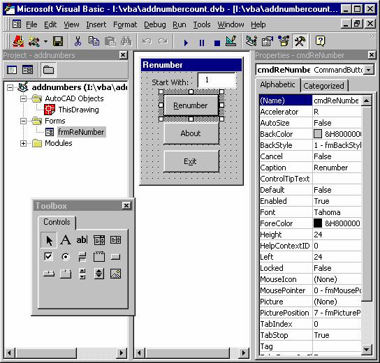
Figure 40 VBA interface
With Visual Basic, the programmer creates a user interface by adding controls from the Toolbox to a Form. To create a push button only requires a selection of the button control in the Toolbox and drawing/placing the control on a Form. It is very easy to create a Form that looks the way it will be used as a program. Buttons to push, Text boxes for entry, Option lists, etc, are a breeze to create, size, and change. The ability to rapidly create a prototype interface for a new program is stunning to say the least. In addition, the resulting Form can be saved and imported into any Windows VBA-enabled program.
Creating a VBA macro
The SwithProfile macro was created to allow the reader/programmer of the is chapter to switch between profiles. The following exercise will show you how to create, save and use the macro.
- From the AutoCAD command prompt type: VBAide (note if AutoCAD returns “Unknown command, you do not have AutoCAD with VBA installed on your workstation).
In the VBA editor create a new module
- From the VBA editor menu pull downs select Insert | Module
- In the code window type in the following
Option Explicit
Sub SwitchProfile()
Dim strProfile As String
strProfile = ThisDrawing.Application.Preferences.Profiles.ActiveProfile
If strProfile = "AutoCAD
2000 Unleashed" Then
' Switch profile
to Existing
ThisDrawing.Application.Preferences.Profiles.ActiveProfile =
"Existing"
Else
' Switch profile to AutoCAD 2000 Unleashed
ThisDrawing.Application.Preferences.Profiles.ActiveProfile =
"AutoCAD 2000 Unleashed"
End If
End Sub
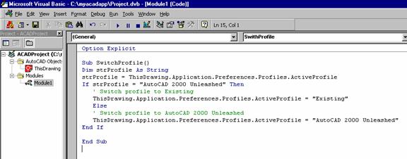
Figure 41 VBA editor code window
- The next VBA macro creates a welcome message
box that includes the login name of the current AutoCAD user.
Sub Welcome()
MsgBox "Welcome:
" & _
ThisDrawing.GetVariable("LOGINNAME")
& vbCr & _
"The AutoCAD 2000
Unleashed VBA macros are now loaded", vbInformation, "AutoCAD 2000
Unleashed"
End Sub
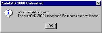
Figure 42 Welcome Message box
Save the VBA program
- From the VBA editor menu select File | Save
- Save as c:\myacadapp\Project.dvb
Programming AutoLISP
LISP acronym history.
AutoLISP, a specialized implementation of the LISP programming language. AutoLISP has become an integral part of AutoCAD.
Programming AutoLISP
You can adapt AutoCAD to your work needs by using AutoLISP to automate repetitive tasks and create new AutoCAD commands. You can write your own AutoLISP programs or use third-party, freeware or shareware AutoLISP programs. This chapter will not attempt to go into the intricacees of teaching you AutoLISP. To become proficient in AutoLISP programming, I recommend you visit your local college or Authorized Autodesk training center and take a course(s) in AutoLISP. In addition, you can pick up some very thick books on AutoLISP and try to teach yourself AutoLISP. I highly recommend anyone starting out in programming AutoCAD to look at learning VBA rather than AutoLISP. The advantages of programming in VBA far outweigh any of AutoLISP’s unique AutoCAD advantages.[FZ1]
Using LISP functions from a toolbar icon.
AutoLISP functions can be called from custom menu pull down or a toolbar icon. One method of having access to a AutoLISP program that is not loaded is to check for the AutoLISP program with AutoLISP within the menu. If the AutoLISP program is not loaded, then the menu will load the program and run the AutoLISP command. If the AutoLISP program is loaded, then the menu will bypass loading the AutoLISP program and run the AutoLISP command. Phew, that was wordy! The toolbar Macro code is much simpler to follow.
- Create a custom icon on the unleashed toolbar
- Set the Button Properties to:
Name: What is
Help: AutoLISP
program to look at the DXF codes of drawing objects
Macro: (if (not c:whatis) (load “whatis.lsp”));WHATIS;
- Apply changes
Running Diesel expressions from the command prompt via AutoLISP.
You can use AutoLISP to experiment with DIESEL at the AutoCAD command prompt.
The following sample routine defines a new command that you can use to enter DIESEL expressions at the command line.
To run/test out Diesel expressions at the command line, create the following diesel.LSP text file and include the following.
;;;
DIESEL.LSP
;;; Lets you
enter DIESEL expressions at the command line
(defun
C:DIESEL ( / dsl )
(while (/= dsl "M=")
(setq dsl (strcat "M=" (getstring
T "\nDIESEL: ")))
(princ (menucmd dsl))
)
(princ)
)
Once this routine is defined, entering diesel on the command line displays a DIESEL prompt. You can enter any DIESEL expression. If it is valid, it returns the result; if it is invalid, it returns an appropriate DIESEL error message. This routine continues to prompt with DIESEL until you press ENTER to give a null response.
Managing programs
File/Directory management
Creating separate directories for drawings, projects, reference documents sounds like something we should all do. Very few people try to do filing with paper documents (save my wife) by placing all the documents in one file drawer (or shoe box). Managing drawings and documents is done in the same logical way that you setup a filling cabinet. Think of your hard drive (or server hard drive) as a filling cabinet. Create and manage your folders and documents within folders with Windows Explorer (woops almost said Windows File manager again). My favorite tool in Windows Explore is Tools | Find | Files or Folders… (alternately press F3). Using F3 with Explorer has helped find many lost files (including co-workers).

If you have completed the previous exercises in this chapter, your directory c:\myacadapp is probably looking quite untidy. Time for some file management you say? Some file management suggestions for the myacadapp directory…
- Place all of the menu related files in a sub directory called c:\myacadapp\menu Menu related files include *.mnu, *.mns, *.mnc, *.mnr, *.mnl, *.bmp
- In the unleashed profile, add c:\myacadapp\menu to your file search path
- Place your VBA projects in a directory called c:\myacadapp\vba. VBA projects have the extension *.dvb. VBA forms have the extension *.frm. VBA modules and have the extension *.bas VBA classes have the extension *.cls
- Place all of the Script files in a sub directory called c:\myacadapp\script. Script files have the extension *.scr.
- Place all of the AutoLISP program in a directory called c:\myacadapp\lisp. AutoLISP program have the extension *.lsp
- Place all of the drawing files in a directory called c:\myacadapp\dwg
- Place all of the support documents in a directory called c:\myacadapp\docs.
Managing project search directories with PROJECTNAME
Once you have the folder structure setup on your hard drive, (local or server) its time to start customizing AutoCAD to take advantage of the file paths for projects. In the previous sections, you have worked with Profiles to manage the AutoCAD file path settings. However, what if you have multiple projects on the go and require different pathing for each project to locate things like Xrefs and support documents? Creating a new Profile for each project could be one solution, but it is not an elegant solution. Especially if you have customizations in place that, use a profile. Luckily, Autodesk was on the ball and included a way of controlling path settings on a per project basis with the Project path option.
Setting up a Project
- From the options form, click the File tab.
- Click the plus [+] next to Project Files Search Path. If no projects are assigned, the label "Empty" is displayed below Project Files Search Path.
- Click Add to create a new folder.
- Type MYACADAPP for the folder name.
- Click Set Current to make the drawing part of the MYACADAPP project.
- Click the plus [+] in front of MYACADAPP.
- Double-click the Empty label.
- In the Browse For Folder dialog box, click the folder c:\ myacadapp
- Also, add the folder c:\myacadapp\dwgs\
- In the Options dialog box, click Apply. Any drawing that is identified as part of the MYACADAPP project will now search this directory before it reports a drawing as Not Found.
- Click OK to exit this dialog box.
The Appload command
The VBA manager provides an excellent way to manage VBA programs on a day-to-day development basis. However, for a tighter, long-term management strategy to control VBA, LISP, and other custom programs loaded into AutoCAD 2000, I[FZ2] recommend looking at the APPLOAD command. If you have used this command in AutoCAD r14 in the past, your initial thoughts on APPLOAD in AutoCAD 2000 might be: "So what? I found the old APPLOAD command practically useless for loading programs. I had to manually click on each LISP routine in the history list and I had to do this each time AutoCAD loaded!" In AutoCAD 2000, the APPLOAD command gets a major "inter-facelift" and capability improvement.

Figure 43 Appload form
The APPLOAD command still handles the chore of loading user-selected ObjectARX Files (*.arx), AutoLISP Files (*.lsp) and ADS (*.exe) programs on a user select-and-load basis. However, the best new feature of the improved APPLOAD command is the addition of the Startup Suite. The icon for this, inside the APPLOAD program, looks like an over-stuffed briefcase The Startup Suite (run from within the APPLOAD program) is capable of automatically loading multiple ObjectARX Files (*arx), AutoLISP Files (*.lsp), VBA Files (*.dvb), ObjectDBX Files (*.dbx), Visual LISP Executables (*.vlx), and Fast-load AutoLISP Format (*.fas). Programs added to the Startup Suit are loaded automatically for each drawing file within AutoCAD 2000. Once added, these programs automatically load in every new session of AutoCAD 2000. Aha — a truly useful feature!

Figure 44 Startup Suite dialogue box
The APPLOAD interface change can make finding the area for creating a history list of favorite programs to load somewhat confusing for the seasoned r14 user. The AutoCAD 2000 APPLOAD does not write a separate text file into each directory from which AutoCAD 2000 starts: no more ugly AutoCAD r14 appload.dfs files in drawing directories. The AutoCAD 2000 APPLOAD information is written into the Windows system registry each time the user runs the APPLOAD command from within AutoCAD 2000. Obviously, the average (or even above-average) AutoCAD user is not going to mess with the Windows system registry to get at the APPLOAD settings. However, for developers, the Windows system registry and the settings in the APPLOAD section for AutoCAD allow yet another method of setting up the loading of a custom application during an AutoCAD 2000 session.
Adding third party components
Guess what… Every one creating custom menus etc. in AutoCAD is a third party…
Helpful tips on customizing AutoCAD
1. Look for an existing solution to your LISP programming problem on the Internet! I recall once writing a LISP that took half a day only to find that someone else had already solved this problem and it was posted free on the Internet.
2. Look beyond the confines of AutoCAD centric Visual Basic solutions. Many Visual Basic example code snippets (and full blown programs) exist on the Internet and can be modified to solve your VBA programming problems in AutoCAD.
3. Scour the AutoCAD news groups for online support. I have seen many tricky VBA and AutoCAD customization problems solved in the Autodesk news groups.
4. Never ever, ever edit the AutoCAD mnu
Rather, create a separate menu and make all changes to only that menu.
5. Load the standard acad.mnu and to a menuload of your custom application menu.
By loading the standard AutoCAD
menu, your application will enjoy the features of the exiting AutoCAD menu with
your customized menu having its own pull downs and toolbars. As the AutoCAD menu changes (yes
6. Think like a 3rd party developer
Everyone that makes changes to the default AutoCAD settings should be thinking like a developer. How will your changes affect others (or your own add-on programs)? Can you easily save your customizations so that you can use your customizations at another work situation? How easy is it for others to user your customizations? Keep in mind; your valuable customizations could turn in to full-blown application for sale to others!
7. Never rename the existing AutoCAD commands. Users like to have predictable results (e.g. when you type: LINE, AutoCAD draws a line not a multiline)
8. Do not “fiddle” with the existing ACAD.pgp file to change the default shortcut keys. Go ahead and create new shortcut keys, but do not mess up the existing keys. Changing existing shortcut keys will only frustrate the end user.
9. Never use variables that other third party developers might use. The following is a paraphrased comments from a fellow CAD manager “Can you believe that 3rd part application using AutoCAD USERS1 variable for there program – I was using them for controlling metric or imperial drawing settings – they must be real dummies to use these settings in a professional program” Pause and think the above over for a moment… What was the CAD manager (and the 3rd party application developer) thinking when using variables that others might use!
10. Try to always write extra comments into your programming code. The person you help understand what you have done, may be yourself!
Using VBA
Opening the Visual Basic Editor
AutoCAD 2000 must be installed with the VBA option enabled (when AutoCAD was installed). To check if the VBA editor is installed in your version of AutoCAD type VBAide at the AutoCAD command prompt. If you receive an AutoCAD error “unknown command” you do not have VBA installed. The fastest way to get to the VBA editor from within side AutoCAD is to press the Alt+F11 keys. Alternately, one can access the VBA Editor from the menu by selecting the Tools | Macro | Visual Basic Editor, or by typing VBAide at the AutoCAD command prompt (remember that this is AutoCAD – and as such there is always more than one way to achieve the same end).
 Running a VBA
macro
Running a VBA
macro
Running the SwitchProfile macro
- From the AutoCAD command prompt type: VBARUN
- Select the macro: C:\myacadapp\Project.dvb!Module1.SwitchProfile
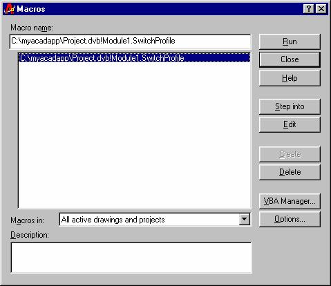
Figure 45 VBArun Macro form
Distributing VBA applications
VBA applications can be distributed two different ways:
![]() Embedded
in an AutoCAD drawing
Embedded
in an AutoCAD drawing
![]() Stored
in a VBA project file
Stored
in a VBA project file
Virus Warning!
An embedded project allows a drawing file to become a
self-contained wrapper for a VBA application or macro. Therefore, drawings containing VBA macros can
also contain viruses. I strongly suggest
that all users start the VBA manager and enable the macro warning options to be
set (click on the Macros button in the VBA manager then click on the
Macros Options button).
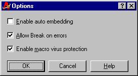
Figure 46 Enable macro virus protection
Distributing your VBA programs within a drawing.
 By embedding the VBA project in a drawing, you
can always be sure the application is loaded and available for use whenever the
drawing is opened. Embedded projects are
limited and not able to open or close AutoCAD drawings because they function
only within the document where they reside. Further, only one embedded project
is allowed per drawing, so you need to extract an embedded project (if one
exists) before a different project can be embedded into a drawing.
By embedding the VBA project in a drawing, you
can always be sure the application is loaded and available for use whenever the
drawing is opened. Embedded projects are
limited and not able to open or close AutoCAD drawings because they function
only within the document where they reside. Further, only one embedded project
is allowed per drawing, so you need to extract an embedded project (if one
exists) before a different project can be embedded into a drawing.
Distributing your VBA programs as a project file.
A separate VBA project file is required when; the project is
used by many people, the project file is updated frequently, or required to
open and close other drawings. VBA
project files have the file extension DVB.
Project DVB files can be distributed by floppy, CD-ROM, email
attachments, website downloads etc.
Project DVB files can then be managed with the VBA manager (called you
guessed it VBAMAN) inside of AutoCAD.
Alternately, project files can be called from menus as demonstrated
earlier in the section Running a
VBA macro from a toolbar icon.
VBAMAN
The VBAMAN command launches the VBA Manager dialog box. From within the VBA manager, the user can extract, embed, create, save, load and unload VBA projects.
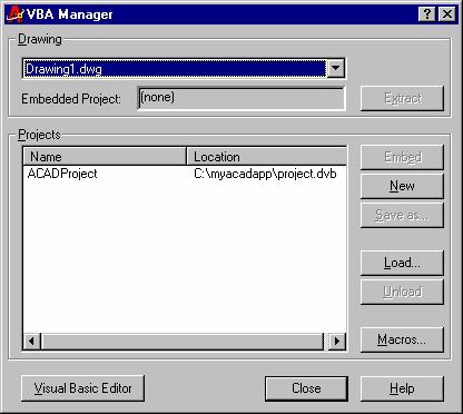
 Figure 47 VBA manager
How to get to AutoCAD 2000’s VBA Help reference.
From inside of AutoCAD’s VBA editor press the F1 key. Next, select the AutoCAD Visual Basic Reference from the resulting dialogue box.
AutoCAD VBA sources on the Internet
![]() Randall
Raath's A Code a Day http://afralisp.hypermart.net/rr/rr.htm
Randall
Raath's A Code a Day http://afralisp.hypermart.net/rr/rr.htm
![]() News
group: Visual Basic Customization Issues with AutoCAD
news://adesknews.autodesk.com/autodesk.autocad.customization.vba
News
group: Visual Basic Customization Issues with AutoCAD
news://adesknews.autodesk.com/autodesk.autocad.customization.vba
![]() VBA
Pro http://www.vbapro.com/
VBA
Pro http://www.vbapro.com/
![]() Contract
CADD Group http://www.contractcaddgroup.com/download/
Contract
CADD Group http://www.contractcaddgroup.com/download/
![]() VBA
Articles http://vbdesign.hypermart.net/cadpages/general_automation.htm
VBA
Articles http://vbdesign.hypermart.net/cadpages/general_automation.htm
Visual Basic (VB) sources on the Internet
![]() Matt
Hart's Visual Basic Help Page http://matthart.com/vbhelp/index.htm
Matt
Hart's Visual Basic Help Page http://matthart.com/vbhelp/index.htm
![]() VB
Helper Home http://www.vb-helper.com/
VB
Helper Home http://www.vb-helper.com/
![]() VB
CodeGuru http://www.codeguru.com/vb/
VB
CodeGuru http://www.codeguru.com/vb/
![]() Visual
Basic Index Page
http://www.spnc.demon.co.uk/index/vb_idx.htm
Visual
Basic Index Page
http://www.spnc.demon.co.uk/index/vb_idx.htm
![]() VbadminCode
http://www.netfokus.dk/vbadmincode/
VbadminCode
http://www.netfokus.dk/vbadmincode/
![]() vbCode
Magician - Visual Basic Resources and Code Examples
http://hjem.get2net.dk/vcoders/cm/
vbCode
Magician - Visual Basic Resources and Code Examples
http://hjem.get2net.dk/vcoders/cm/
![]() VBnet,
The Visual Basic Developers Resource Centre
http://www.mvps.org/vbnet/index.html
VBnet,
The Visual Basic Developers Resource Centre
http://www.mvps.org/vbnet/index.html
![]() VBWire
- Visual Basic News & Information Source http://vbwire.com/
VBWire
- Visual Basic News & Information Source http://vbwire.com/
![]() Visual
Basic World - The leading online information source for Visual Basic
developers. http://www.vb-world.net/
Visual
Basic World - The leading online information source for Visual Basic
developers. http://www.vb-world.net/
![]() Visual
Basic Programmers Journal http://www.vbpj.com/
Visual
Basic Programmers Journal http://www.vbpj.com/
![]() Planet
Source Code. http://www.planet-source-code.com/vb/
Planet
Source Code. http://www.planet-source-code.com/vb/
Using AutoLISP
Loading an AutoLISP program
From the AutoCAD command line
The method of loading an AutoLISP program from the AutoCAD command prompt requires the user to know the location of the AutoLISP file (if it is not on the AutoCAD search path). To load an AutoLISP program WHATIS.LSP without supplying the file path information do the following:
![]() From
the AutoCAD command prompt type: (load WHATIS.LSP)
From
the AutoCAD command prompt type: (load WHATIS.LSP)
![]() To
run the WHATIS.LSP program, type: WHATIS
To
run the WHATIS.LSP program, type: WHATIS
Drag and drop

My preferred method for quickly loading an AutoLISP program (occasional usage
only) is to select the AutoLISP file from Windows Explorer, drag and drop the
AutoLISP file onto the AutoCAD screen.
To run the dropped program, type the applicable command for the program.
MNL file – an automatically loading lisp file associated with a menu.
Your custom AutoLISP functions can be defined and loaded with your custom menu automatically in as separate text file text file. The text file has the same name as your custom menu with the extension MNL. The MNL is referred to as a menu LISP file. This file can contain AutoLISP expressions that are loaded into memory when a menu file with the same file name is loaded.
Creating the unleashed.MNL
- From Windows Explorer, create a new text file in C:\MYACADAPP\
- Rename the new textfile.txt to unleashed.MNL
- To have the unleashed.MNL display a Welcome message box from VBA add the following:
;;;
Unleashed menu MNL file
;;;
This file defines and loads AutoLISP and VBA macros
;;;
For the Unleashed menu
;;;
;;;
----------------------------------------------------------
;;;
Create a Startup function for the Unleashed menu
(defun-q
UNLEASHEDSTARTUP ( )
; load the VBA welcome macro
(command "-VBARUN"
"c:/myacadapp/project.dvb!module1.welcome")
)
; end of defun Unleashed
;;;
Append the Unleashed Startup to any existing startup
(setq
S::STARTUP (append S::STARTUP UNLEASHEDSTARTUP))
;;;
Notify the user at the AutoCAD command prompt,
;;;
that this MNL file has loaded
(princ
"AutoCAD 2000 Unleashed Menu MNL is loaded...")
(princ)
Optional
To have the unleashed menu pop down inserted into the menu pull down area (this is an automation of doing a menuload and manually selecting the location of the pull-down menu), Add the following lines of code to the unleashed.MNL ;;;
Unleashed menu MNL file ;;;
This file defines and loads AutoLISP and VBA macros ;;;
For the Unleashed menu ;;; ;;;
---------------------------------------------------------- ;;;
Check for unleashed menu inserted as a pull down (if
(not (wcmatch (strcase (getvar "menuname"))
"*UNLEASHED")) ;;;
Check for pull down insert (progn (menucmd "Gunleashed.pop1=-")
; unload the unleashed pop down if loaded.. (setq response "") (setq counter 0) (while (= response "") (setq counter ( + counter 1)) ; count each pull down (setq response (menucmd (strcat "P" (rtos
counter 2 0) ".1=?"))) ) ; Insert the unleashed pull down (menucmd (strcat "P" (rtos (-
counter 1) 2 0) "=+Unleashed.pop1")) ); end progn (princ) );
end if |
4. Save the unleashed.MNL
AutoCAD LISP Help reference.
To find AutoCAD help for AutoLISP press F1 while inside AutoCAD. From the Contents tab of the AutoCAD help form select Visual LISP and AutoLISP | Shortcut link to the AutoCAD Visual LISP Help
![]()
Figure 48 Shortcut link to the AutoLISP Reference
LISP sources on the Internet.
![]() AfraLisp-The
Southern African AutoCAD/AutoLISP/VBA Website http://afralisp.hypermart.net/
AfraLisp-The
Southern African AutoCAD/AutoLISP/VBA Website http://afralisp.hypermart.net/
![]() AutoCAD
Shareware Clearinghouse http://www.cadalog.com/
AutoCAD
Shareware Clearinghouse http://www.cadalog.com/
![]() The
CADdepot - AutoCAD/CAD, free AutoLISP, arx, ads, vba, shareware downloads.
http://www.caddepot.com/
The
CADdepot - AutoCAD/CAD, free AutoLISP, arx, ads, vba, shareware downloads.
http://www.caddepot.com/
![]() CADShack
http://www.cadshack.com/
CADShack
http://www.cadshack.com/
![]() AutoLisp
Utilities for AutoCAD http://ucad1.uccb.ns.ca/acad/util.htm
AutoLisp
Utilities for AutoCAD http://ucad1.uccb.ns.ca/acad/util.htm
![]() CADALYST
Get the Code http://www.cadonline.com/code/
CADALYST
Get the Code http://www.cadonline.com/code/
Integrating hyperlinks
To this point, you have concentrated on making changes to the AutoCAD interface to help navigate the drawing interface and speed up the process of automating drawing tasks. Next, you will add intelligence to drawings via hyperlinks to other documents on your hard drive , your server, or over the Internet. You can create both absolute and relative hyperlinks in your AutoCAD drawings. Absolute hyperlinks store the full path to a file location. Relative hyperlinks store a partial path to a file location, relative to a default URL or directory you specify using the HYPERLINKBASE system variable.
HYPERLINKBASE
Specifies the path used for all relative hyperlinks in the drawing. If no value is specified, the drawing path is used for all relative hyperlinks. Therefore, to reference documents in the same directory as the drawing, not file path needs to be supplied . Think of the Hyperlinkbase as the directory (or on the internet website folder) that the reference documents are located under.
Creating a Hyperlink to a product specification documents.
In the next exercise, you will create three hyperlinks in an AutoCAD drawing to documents on the local hard drive. The first documents you will link to is a Microsoft Word document containing product information. The second hyperlink will point to an Adobe Acrobat documents. The third link will point to an AutoCAD drawing detail.
Creating a Hyperlink to a Microsoft word document:
- Create a Microsoft word document and save as c:\myacadapp\spec.doc
- From the AutoCAD pull down menu select: Insert | Hyperlink
Alternately press CTRL+K
1.
Select the drawing object to link the Hyperlink
to (if you have an empty drawing, create a line or rectangle and start over)
2. On the Hyperlink form fill in the following:
Link to file or URL: spec.doc
Hyperlink Description (optional):
Drawing Specification
- Press OK
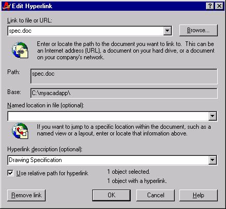
Figure 49 Hyperlink to a local MSword document
Creating a Hyperlink to an Adobe acrobat PDF document
1. Press CTRL+K
2. Select an object in the drawing to Hyperlink
3. On the Hyperlink form fill in the following:
Link to file or URL: Andersen.pdf
Hyperlink Description (optional):
Andersen door details
- Press OK
Creating a Hyperlink to an AutoCAD drawing detail.
1. Create an AutoCAD drawing (draw some rectangles, whatever) and save as c:\myacadapp\detail.dwg
2. Press CTRL+K
3. Select an object in a drawing (a drawing other than the detail.dwg) to Hyperlink
4. On the Hyperlink form fill in the following:
Link to file or URL: detail.dwg
Hyperlink Description (optional):
door hardware details
- Press OK
Open, Copy, or Edit a Hyper link in a drawing
- Select the object with a hyperlink symbol on it.
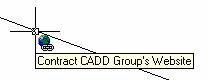
Figure 50 Mouse over on a hyperlinked
drawing object
2. Next,
right-click the object and select the Hyperlink option.
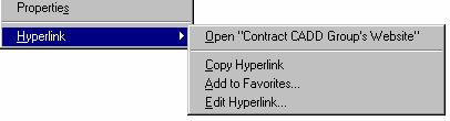
Figure 51 Right-click a drawing hyperlink

Integrating Web functionality
Creating Hyperlinks to Internet documents.
To create hyperlinks to Internet documents, use the same HYPERLINK (or CTRL+K or launch from the Insert pull down) command and interface to link local documents. The only difference is that when you browse for files, use the Search the web button.
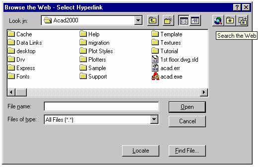
Figure 52 Search the Web button on the Browse the Web form
To search the Internet (Web), AutoCAD uses the Select Hyperlink interface. This form is very similar to an Internet browser. Pressing the home icon will take you to the User Resource Locator (URL) stored in the AutoCAD variable INETLOCATION.
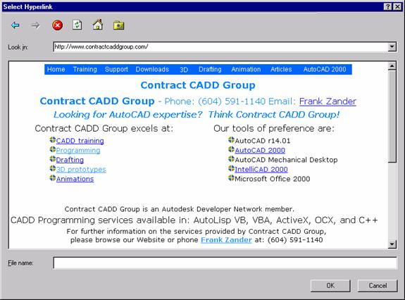
Figure 53 Select Hyperlink form
INETLOCATION
The INETLOCATION variable stores the Internet location used by the BROWSER command and is the home location for the Select Hyperlink form.
BROWSER
The BROWSER command launches your default Internet browser from within AutoCAD.
Creating a Hyperlink to a website.
1. Press CTRL+K
2. Select an object in the drawing to Hyperlink
3. On the Hyperlink form fill in the following:
Link to file or URL: www.contractcaddgroup.com
Hyperlink Description (optional):
Contract CADD Group’s website
Uncheck - Use relative path for
hyperlink
4.
Press OK
Creating a Hyperlink to a document on the Internet
1. Create a dimension
2. Press CTRL+K
3. Select the dimension to Hyperlink
4. On the Hyperlink form fill in the following:
Link to file or URL: http://www.contractcaddgroup.com/articles/altdimdecfeet.htm
Hyperlink Description (optional):
Dimension style settings
5.
Uncheck - Use relative path for
hyperlink
6. Press
OK
Creating a Hyperlink to a DWF on the Internet
1. Press CTRL+K
2. Select an object in the drawing to Hyperlink
3. On the Hyperlink form fill in the following:
Link to file or URL: http://www.contractcaddgroup.com/images/webdwg/rink.dwf
Hyperlink Description (optional):
Hockey rink layout
4.
Uncheck - Use relative path for
hyperlink
5. Press
OK
Other reference sources
Newsgroups
Take Five Break Room
news://adesknews.autodesk.com/pn.take5
It is never too crowded around the Take Five water cooler. Come chat with each
other on Autodesk or Autodesk product related industry topics not represented
in the existing forums. This is the place to connect with the Autodesk online
community in a casual setting. Messages that are deemed inflammatory, non-constructive,
or unrelated to the aims of the Autodesk discussion groups will be removed at
Autodesk's sole discretion.
CAD Manager Café
news://adesknews.autodesk.com/pn.cadmanager
This newsgroup is a place for networking, discussing common issues and industry
standards for CAD Managers around the world.
Classified Ads
news://adesknews.autodesk.com/pn.classifieds
Have hardware, books or services for sale? Looking for these items? Want to
advertise a cool site on the Web? Here is the place to post your ad or go
shopping.
AutoCAD Express Tools
news://adesknews.autodesk.com/autodesk.expresstools
Support, suggestions and usage relating to AutoCAD Express Tools.
Download the 2000 express tools free from Autodesk at:
http://www.autodesk.com/products/acadtool/#dlinfo
Visual Basic Customization Issues with AutoCAD
news://adesknews.autodesk.com/autodesk.autocad.customization.vba
Visual LISP™, AutoLISP® and General Customization
Issues
news://adesknews.autodesk.com/autodesk.autocad.customization
Plotstamp program from Autodesk
AutoCAD 2000 plot stamping utility from http://www.autodesk.com/support/autocad/util2000.htm.
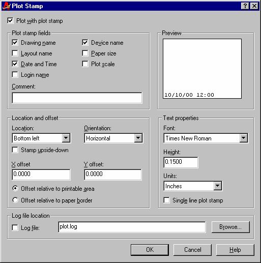
Figure 54 Plot Stamp interface
Chapter summary
Upon completion of the practical example exercises of this chapter, the user will have gained the skills to create or integrate menus and macros to automate AutoCAD. The user will also have gained an understanding of the issues involved in customizing AutoCAD and how to avoid common integration/customization mistakes encountered when customizing or developing an add-on (third party) application for AutoCAD.
Figure index
Figure
3 Export Existing Profile
Figure
4 adding C:\myacadapp to the AutoCAD Search Path
Figure
5 Export unleashed profile
Figure
6 Reset warning dialogue box
Figure
7 Copying the AutoCAD 2000 desktop icon
Figure
8 AutoCAD Unleashed Icon
Figure
9 AutoCAD Unleashed Icon Properties
Figure
11 Creating a New | Text Document in C:\MYACADAPP
Figure
13 Editing the Unleashed.mnu in notepad
Figure
14 selecting the unleashed.mnu in the dialogue box.
Figure
15 MNU overwrite message dialogue box.
Figure
16 Unleashed menu loaded
Figure
17 Menuload Menu Customization dialogue box
Figure
19 Unleashed pull down inserted between Window and Help pull downs.
Figure
21 Creating the New AutoCAD 2000 Unleashed Toolbar
Figure
22 Empty AutoCAD 2000 Unleashed Toolbar
Figure
23 Find the Calculator Icon
Figure
24 Calculator Icon Button Properties
Figure
25 Mouse over the calculator icon
Figure
26 unleashed.mns in notepad after doing toolbar drag and drop
Figure
27 Right-click toolbar with Customize....
option
Figure
28 Button Properties for MNS editor
Figure
30 Switch Profiles Button Properties
Figure
32 Unleahsed Flyout Toolbar
Figure
34 Flyout Properties form
Figure
35 Displaying the Unleashed Flyout toolbar
Figure
36 Filler up with Diesel
Figure
37 AutoCAD Layer Pull down list box
Figure
38 Modemacro with $(getvar,clayer)
Figure
39 Diesel Expressions in a pull down menu
Figure
41 VBA editor code window
Figure
44 Startup Suite dialouge box
Figure
46 Enable macro virus protection
Figure
48 Shortcut link to the AutoLISP Reference
Figure
49 Hyperlink to a local MSword document
Figure 50 Mouse over on a
hyperlinked drawing object
Figure
51 Right-click a drawing hyperlink
Figure
52 Search the Web button on the Browse the Web form
Figure
53 Select Hyperlink form
Figure
54 Plot Stamp interface